A SerDes system for high speed digital data typically requires equalization to counter act the high loss in the channel that closes the data eye pattern at the receiver side. This equalization is often applied at the transmit and receive sided of the channel.
The transmit equalization typically is achieved with feed-forward equalization (FFE). xxxx
FFE is an equalization technique that corrects the received waveform with information about the waveform itself and not information about the logical decisions made on the waveform. FFE basically acts like a FIR (finite impulse response) filter and uses the voltage levels of the received waveform associated with previous and current bits to correct the voltage level of the current bit. One key thing to remember when working with FFE is that the equalization is performed on the actual waveform. At no point in the FFE algorithm are logical decisions made (is this bit a 1 or a 0?). Instead, FFE is only concerned with correcting voltage levels in the waveform.
A typical signal flow diagram for a 4-tap FFE is shown here:
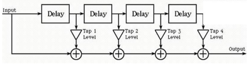
Delay represents the time delay for one unit bit time interval. This diagram can be for an FFE with one pre-cursor, two post-cursors, and with Tap 2 as the main tap.
See FFE detail (listed as Tx FIR) in References > Equalization Introduction and Tx FIR Equalization.
Follow the steps to define the FFE, setup the FFE analysis, run the analysis, and display the FFE analysis results. Observe the FFE frequency domain characteristic and its data waveform response.